


A domestic light switch in the UK must be wired only after isolating the circuit at the consumer unit and proving it is dead with a reliable tester. Use insulated tools; identify conductors by correct colour coding or test results; connect the permanent live to the common terminal and the switched live to L1; keep neutrals insulated; and ensure earths are secured. Tighten terminals, replace the cover and restore power to test operation; further guidance and common setups follow.
Key Takeaways
- Isolate the circuit at the consumer unit, label the breaker, and verify the circuit is dead with a reliable voltage tester before touching wires.
- Identify conductor colours and roles (modern: brown live, blue neutral, green/yellow earth; legacy: red live, black neutral) and sleeving where needed.
- Connect live (brown/red) to the switch common; switch live to L1; keep neutrals insulated and not connected to the switch.
- Use appropriate insulated tools, CE/UKCA-certified switch and connectors, tighten terminals to the manufacturer’s torque, and arrange cables neatly.
- Call a qualified electrician for consumer unit work, RCD/earthing uncertainty, kitchen/bathroom circuits, or any notifiable alterations.
Quick Answer: How to Wire a Single‑Pole Light Switch
Begin by isolating power at the consumer unit and verifying the circuit is dead with a reliable tester. The single‑pole switch connects the live feed and the switched live to control the lamp; the neutral remains joined at the light fitting.
The installer identifies the permanent live (often brown or red) and the switched live (often black with brown/red tape, or brown if sleeved) and secures them to the switch’s common and L1 terminals, respectively. Earth conductors, where present, are bonded to the switch earth terminal or backbox.
Terminations must be neat, with conductors stripped to the correct length, screws tightened to the manufacturer’s torque, and sleeving applied to exposed conductors. After connections are made, the switch is mounted, and the faceplate is secured. Final checks include verifying mechanical operation and continuity of live to the lamp when switched, and ensuring that the workmanship supports the occupant’s autonomy and safety.
Turn Off the Circuit and Prove the Circuit Is Dead
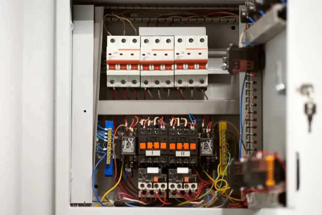
Isolate the circuit at the consumer unit and lock or label the breaker or fuse to prevent re-energisation. The person working on the switch guarantees the correct circuit is off by selecting the labeled breaker or removing the cartridge fuse, then secures it against inadvertent switching.
After isolation, they use a proven live-dead voltage tester or a two-pole voltage tester at the switch terminals and any accessible downstream conductors. Test the tester on a known live source before and after checking to verify functionality. Probe all conductors present, including neutrals and earths if accessible, since incorrect assumptions can endanger freedom of action. Once the instrument shows zero volts on each conductor, the circuit is considered dead.
The person records or tags the isolation and proceeds only when confident of the absence of voltage. Maintaining this disciplined verification preserves autonomy by minimising reliance on assumptions and protecting against unexpected energisation during the work.
Tools and Parts for Replacing a Light Switch
A compact kit of reliable tools and correctly rated parts guarantees the replacement proceeds safely and efficiently. The list should include an insulated screwdriver set, a voltage tester or non-contact detector to confirm dead circuits, wire strippers, a small pair of pliers, and a compact socket or nut driver if fixing screws vary.
Spare screws and wall anchors suited to the backbox material are practical. A quality single or double pole switch rated for UK mains (BS EN standards) and matching plate finish assures longevity. Suitable connector blocks (terminal blocks) or insulated ferrules for stranded conductors promote secure terminations. Electrical tape and marker labels aid identification without altering wiring. A torch or headlamp supports visibility in dim spaces. A small tray for screws prevents loss.
All items should be CE marked or UKCA certified where applicable. Choosing the proper tools and certified parts facilitates confident, independent replacement while maintaining safety and compliance.
Identify UK Cable Colours and Conductor Roles
With tools and parts ready, attention turns to identifying UK cable colours and each conductor’s role before any connections are touched. The electrician observes modern UK colour codes: brown is live (line), blue is neutral, and green/yellow is earth (protective). Older installations may show red for live and black for neutral; spotting age and labelling matters. Multiple cables and switched lives can introduce sleeved conductors. Brown sleeving on a blue conductor indicates it is carrying live potential for switching.
The practitioner values autonomy and clear labeling: use marker tape or permanent labels to record roles before isolating circuits. Visual checks and continuity tests (with power isolated) confirm which conductor feeds the circuit, returns from the switch, or bonds earths. Documentation and photos preserve choices for later work or future occupants, supporting safe, independent maintenance without assuming fixed patterns in every home.
- Modern colours: brown (L), blue (N), green/yellow (E).
- Legacy colours: red (L), black (N).
- Sleeving indicates reassigned conductors.
Step‑By‑Step: Wiring a Single‑Pole Light Switch
Begin by confirming the circuit remains de-energised and that the appropriate protective gear is worn; then lay out the switch, screws, and identified cables for easy access. The installer removes the faceplate, loosens terminal screws, and checks conductors for damage. The live (brown or red) is routed to the common terminal (COM), and the switched live to the L1 terminal; neutrals are kept insulated and not connected to the switch.
Conductors are stripped to the correct length, inserted straight into terminals, and screws tightened to the manufacturer’s torque to prevent overheating. Earth conductors, if present, are connected to the switch’s earth terminal or a metal back box, ensuring continuity. After wiring, the installer neatly arranges cables to avoid strain, fits the faceplate, and secures it firmly. Before re-energising, a continuity or insulation test confirms correct connections. Finally, the circuit is energised and the switch operated to verify reliable, free control of the light.
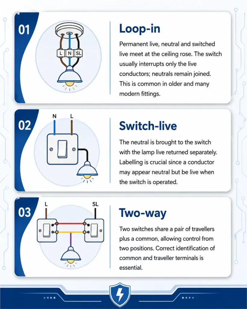
Common Wiring Setups (Loop‑In, Switch‑Live, Two‑Way)
Although domestic lighting circuits can be configured in several ways, three patterns account for the vast majority of UK installations: loop‑in (junction at the ceiling rose), switch‑live (neutral at the switch), and two‑way (two switches controlling one fitting). The descriptions that follow provide clear, compact outlines so a confident DIYer can recognise each arrangement and choose appropriate wiring and accessories.
Test the Switch, Secure Connections and Finish Installation
Once wiring is complete, the installer must test the switch operation, verify all connections are secure, and restore the finish fittings. The tester first restores power and operates the switch, watching the light and any associated indicators. Each position is checked for correct function; for two‑way circuits, both switches are tested. If flicker, buzzing or unexpected behaviour appears, power is cut, and terminals re‑examined.
Next, terminal screws are tightened to manufacturer torque guidance where available; insulated sleeving is confirmed on live conductors and earth continuity is verified. Cable clamps and entry points are checked so no conductor is strained when the switch is seated.
Once satisfied, the faceplate is aligned and secured, guaranteeing no wiring is trapped,d and the plate sits flush. A final visual inspection guarantees that labeling or notes are added if non‑standard wiring was used. The installer leaves the area tidy, enabling the occupant to use the circuit confidently and independently.

UK Safety Rules, Legal Limits and When to Call an Electrician
Having completed functional tests and secured fittings, attention must turn to the legal and safety framework governing electrical work in the UK. The guidance emphasises that minor tasks like replacing a simple switch are permitted for competent homeowners, but more complex work altering circuits, adding new circuits, or working in kitchens and bathrooms falls under a controlled, qualified scope.
Compliance with Part P of the Building Regulations and BS 7671 wiring rules is essential; uncertified work can invalidate insurance and create danger.
- Call a qualified electrician if work involves consumer units, circuit alterations, or any uncertainty about earthing or RCD protection.
- Use registered installers for notifiable work or obtain Building Regulations approval; keep certificates for future resale and insurance.
- Prioritise personal freedom by learning basics safely, but respect legal limits to avoid liability, injury, and costly rectification.
The balance preserves autonomy while acknowledging responsibilities for public safety and legal compliance.
Frequently Asked Questions
Can I Replace a UK Light Switch With a Smart/Remote Switch Instead?
Yes, they can replace a UK light switch with a smart or remote switch, provided the smart unit matches wiring and load, neutral requirements are met, and installation follows regulations or uses a qualified electrician for safety and legal compliance.
How Do I Wire an Outdoor/Floodlight With a Switch and Photocell?
They should connect the permanent live to the photocell live, the photocell switched live to the floodlight and to the manual switch input, the floodlight neutral to the photocell neutral, and the earths together; the manual switch overrides the photocell when wired as intended.
Can I Move a Light Switch to the Opposite Side of the Room?
Yes. They can relocate the switch to the opposite side, provided cable routes, consumer unit capacity, and local wiring regulations are respected; a qualified electrician should assess existing cables, install an appropriate switch loop, and obtain any required permissions.
What Causes a Switch to Trip an RCD or Blow a Fuse?
A faulty switch trips an RCD or blows a fuse when it creates earth leakage, short circuits, or overloads; damaged insulation, loose connections, water ingress, or incorrect wiring commonly provoke protective devices to interrupt the circuit.
How Do I Wire a Switch for a Ceiling Fan and Light Combo?
They should run separate switched lives: one live to the fan, one live to the light, with a shared neutral and earth; each switch controls its respective live conductor, ensuring fusing, RCD protection, and safe isolation before work.
Conclusion
To sum up, the guide stresses that wiring a single‑pole light switch in the UK requires careful isolation, correct identification of the brown (live), blue (neutral), and green/yellow (earth) conductors, and secure connections when following loop‑in or switch‑live arrangements. It emphasises using proper tools, testing with a proven voltage tester, and complying with UK safety rules and legal limits. For any uncertainty, especially with multi‑way or old wiring, a qualified electrician should be called.