




A cause-and-effect matrix for fire alarm systems is a concise, rule-based chart linking detector and manual inputs to required alarms, controls, and supervisory outputs. It guarantees predictable, code-compliant responses and reduces reliance on memory during incidents. Inputs and outputs are chosen for relevance, reliability, and testability, then mapped by zone into a grid with defined actions and fail-safes. Validate, test, document, and include the matrix in handover and training; continue with practical examples and test checklists.
Key Takeaways
- A cause-and-effect matrix maps fire alarm inputs (detectors, manual pulls) to specific outputs (alarms, suppression, HVAC control) for predictable system behavior.
- It documents prioritised, code-compliant responses for each input, including timing, fail-safe actions, and manual intervention points.
- Building the matrix involves surveying the site by zone, listing inputs/outputs, and defining responses at each input-output intersection.
- Testing and validation require scenario-based tests, timing verification, independent review, and documented pass/fail checklists with formal sign-off.
- Handover includes compliance mapping, operator training, quick-reference cards, controlled change procedures, and retained test records for audits.
What a Cause-and-Effect Matrix Is (And Why It Matters)
A cause-and-effect matrix is a structured chart that links specific inputs such as detector activations, manual pulls, or supervisory signals to defined outputs like alarms, notifications, and control actions; it documents how a fire alarm system should respond under various conditions and guarantees consistent, predictable behavior. The matrix clarifies responsibilities and preserves operational freedom by providing a cause-and-effect matrix for fire alarm systems, making system behavior explicit and auditable.
It enables designers, operators, and authorities to verify that responses align with safety goals and regulatory limits without ambiguity. By mapping causes to effects, the document reduces reliance on memory or ad hoc decisions during incidents, allowing personnel to act decisively within preset options. It supports modular changes: adjustments to zones, devices, or sequences can be made without undermining overall logic. Additionally, the matrix informs testing and maintenance by defining expected outcomes for each input, so verification is focused and efficient. In sum, it is a compact, authoritative blueprint that balances safety, flexibility, and accountability.
How to Choose Inputs and Outputs for a C&E Fire Alarm Matrix
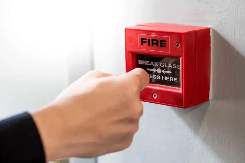
Selecting inputs and outputs for a cause-and-effect fire alarm matrix requires prioritising relevance, reliability, and regulatory compliance so that every listed signal directly supports an intended safety function. The process identifies sensors, manual stations, supervisory devices, and control interfaces as inputs, and alarms, notification appliances, suppression commands, HVAC overrides, and elevator controls as outputs. Each candidate I/O is evaluated for failure modes, testability, and required response time. Redundancy is applied selectively to critical paths while avoiding unnecessary complexity that restricts operational freedom.
Mapping focuses on clear, unambiguous actions: which inputs activate which outputs under defined conditions, including sequence and timing. Documentation records rationale, addressability, and priority levels to facilitate audits and future modification. The selection respects applicable codes and owner risk tolerance but preserves flexibility for alternative mitigation strategies. The resulting matrix balances safety, maintainability, and adaptability so facility operators retain control without compromising life-safety obligations.
How to Translate Codes and Facility Priorities Into Matrix Logic
Conformance with code requirements and alignment with facility priorities translate into explicit logic statements that govern which inputs trigger which outputs, under what conditions, and with what sequence and timing. The planner maps mandatory code responses (alarms, notifications, shutdowns) to matrix rules, then layers facility preferences life-safety first, asset protection, operational continuity so conflicting outcomes are resolved by precedence.
Each rule specifies criteria: input type, zone, verification level, time delay, and conditional modifiers (e.g., supervisory status, maintenance mode). Sequencing and timing parameters guarantee coordinated actions: immediate evacuation signals, staggered equipment shutdowns, or delayed notifications to reduce false alarms. Documentation records rationale, exceptions, and acceptable risk tolerances so the logic remains auditable and adaptable. The resulting matrix is modular, enabling selective overrides for special events while preserving core protections mandated by code. This approach preserves operational freedom within a safe, rule-governed framework.
How to Build a Simple Cause-and-Effect Matrix for Your Site (Step-by-Step)
Begin by surveying the site to identify all relevant inputs (detectors, pull stations, supervisory devices) and outputs (alarms, notification appliances, control relays) and group them by fire zones and critical systems. Next, list each input and output on a simple grid: rows for inputs, columns for outputs. For each intersection, define the desired response: alarm, delay, supervisory notification, or suppressed, based on safety priorities and operational constraints.
Assign clear conditions and timing parameters (e.g., immediate, 30-second verification) and note any prerequisites like power or system health. Incorporate manual actions and reset requirements. Review dependencies where one output affects another (shutting down HVAC, releasing holds) and document fail-safe behaviors for loss of power or communications. Validate entries against applicable codes and stakeholder needs. Finally, simulate scenarios with stakeholders, adjust entries for practicality, and freeze the matrix version for implementation and testing, preserving a change log for future revisions.
Common C&E Matrix Patterns and Standard Output Sequences
When standardised patterns are applied, cause-and-effect matrices for fire alarm systems exhibit recurring output sequences: alarm initiation, verification/delay, staged notification, system shutdowns, and supervisory alerts that reflect safety priorities and building operations. The matrix codifies predictable responses: detectors trigger initial signals, verification logic reduces false alarms, and escalation paths control what devices activate and when. Common patterns balance occupant safety with operational continuity, enabling selective evacuation, phased notifications, or immediate full alarm depending on zone and severity. Freedom-oriented operators appreciate clear, minimal constraints that still guarantee reliable outcomes.
- Single-zone immediate alarm → horns/strobes + notification to monitoring service.
- Verified alarm → short delay, then staged public address and elevator recall.
- Supervisory/trouble → central alert to facilities with no audible evacuation.
These sequences serve as templates; they are adapted to site-specific risks, occupancy patterns, and regulatory requirements while preserving predictable, auditable behavior.
How to Test, Validate, and Document the Matrix (Checklists & Sign-Offs)
Having established common cause-and-effect sequences and their site-specific adaptations, the next step is to verify that the matrix performs as intended under real-world conditions through systematic testing, validation, and documentation. Tests should follow a structured plan: simulated inputs for each cause, observation of every intended output, timing verification, and confirmation of interlocks and supervisory signals. Validation requires independent review against design criteria and regulatory requirements, with discrepancies logged and resolved.
Documentation must include concise checklists for each test scenario, pass/fail criteria, measured timings, and initials of responsible technicians. A formal sign-off procedure ties accountability to release: designers, commissioning engineers, and facility managers sign sequentially after corrective actions are complete. Records are retained for audits and future changes, enabling freedom to modify the system confidently. Clear, minimal records reduce ambiguity while preserving traceability and ensuring the matrix reliably directs protective actions without unnecessary constraint.

Troubleshooting False Activations and Unintended Outputs
Investigate false activations and unintended outputs methodically to isolate root causes and restore reliable operation. The process centers on objective diagnostics, separating environmental, hardware, and logic-related causes. Technicians verify sensor placement, contamination, and electromagnetic interference; they review wiring, grounding, and module health; and they audit the cause-and-effect logic for unintended command paths. Documentation of each test and observation preserves freedom to iterate without repeating errors.
- Test environmental and sensor factors: inspect detectors, measure dust, temperature, and airflow; simulate everyday conditions to reproduce false trips.
- Verify wiring and hardware integrity: perform continuity, insulation, and loop-resistance checks; swap modules to rule out intermittent faults.
- Evaluate matrix logic and configurations: trace inputs to outputs, check isolate/disable states, and examine timers, cross-zone logic, and supervisory thresholds.
Conclusions focus on corrective actions that restore predictability while allowing operators to regain confident, flexible control.
Compliance, Handover, and Operator Training for the Matrix
After isolating and correcting false activations, attention shifts to confirming that the cause-and-effect matrix meets regulatory requirements and that operators receive the information and training needed for safe, predictable operation. Responsibility for compliance is documented, with test records, standards mapping, and a clear handover package that supports autonomous facility management. Training emphasises decision-making freedom within defined safety limits: when to act, when to escalate, and how to override safely. Operators receive concise manuals, quick-reference cards, and scenario-based drills that mirror real conditions. Regular audits verify that changes preserve compliance and operator competence, and updates to the matrix follow a controlled change procedure.
| Item | Purpose |
| Compliance Map | Links matrix to codes |
| Handover Pack | Provides system baseline |
| Training Plan | Defines skills and drills |
| Quick References | Supports on-the-spot choices |
| Audit Schedule | Guarantees ongoing conformity |
This approach balances regulatory certainty with operational independence.
Frequently Asked Questions
Can Third-Party Systems (Hvac/Scada) Trigger or Be Triggered by the Fire Matrix?
Yes. He notes third-party systems like HVAC or SCADA can both trigger and be triggered by the fire matrix, provided authorised interfaces, strict access controls, and clear fail-safe rules exist to preserve safety, autonomy, and operational freedom.
How Do Firmware Updates or Panel Replacements Affect Existing C&E Logic?
Firmware updates or panel replacements can alter, reset, or corrupt existing C&E logic; the technician must verify, migrate, and validate settings, preserving autonomy through documented backups, staged testing, and configuration control to prevent unintended interlocks.
What Cybersecurity Measures Protect Remote C&E Configuration Access?
Encrypted VPN tunnels, multi-factor authentication, role-based access control, strict change auditing, least-privilege accounts, regular patching, network segmentation, intrusion detection, and physical token use protect remote configuration, preserving operator autonomy and secure, auditable control.
Who Legally Owns the C&E Documentation After Contractor Turnover?
The owner retains legal ownership of cause-and-effect documentation after contractor turnover, unless a contract explicitly assigns rights otherwise; contractors may keep copies, but intellectual property and operational control typically transfer to the facility owner per agreement.
Are There Insurance Implications for Customized Non-Standard Matrix Logic?
Yes. Insurers may charge higher premiums or impose exclusions for bespoke, nonstandard logic due to increased risk and testing complexity. Owners often must prove rigorous validation, documentation, and maintenance to satisfy underwriting and claims requirements.
Conclusion
Cause-and-effect matrix for fire alarm systems: A clear, well-designed cause-and-effect matrix makes fire alarm systems predictable, code-compliant, and easier to operate. By selecting appropriate inputs and outputs, encoding facility priorities, and documenting logic, stakeholders reduce false activations and guarantee required responses. Systematic testing, validation, and training support reliability and a smooth handover. Regular review and troubleshooting preserve performance as facilities change. Ultimately, a concise, maintained C&E matrix protects occupants and assets while simplifying maintenance, compliance, and emergency decision-making.